Design Through Process Control: A novel design methodology for additive manufacturing
This project was a cooperation between Stian Vestly Holte and Kit Wai Chan.
PROCESS CONTROL
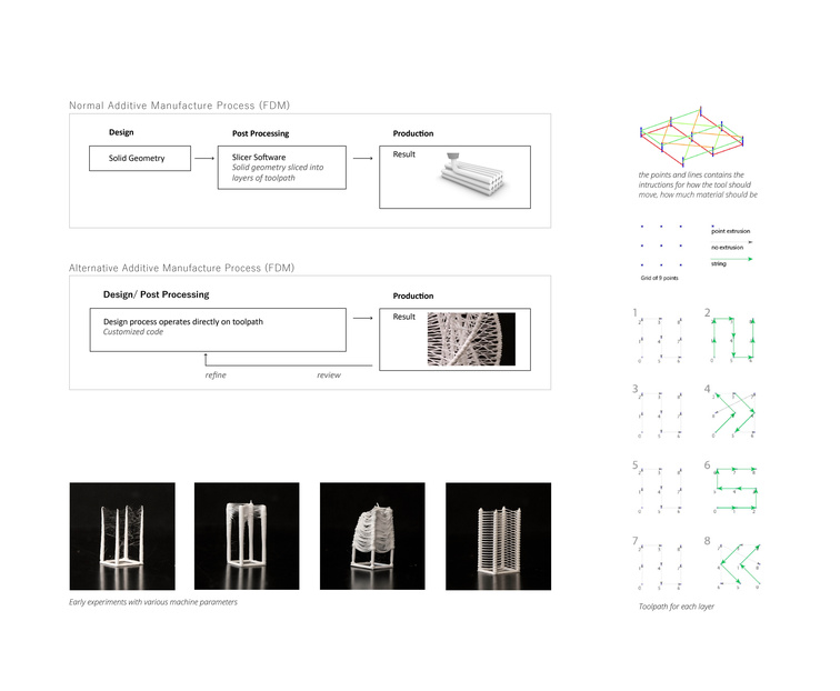
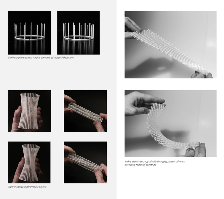
The project explores alternative methods of design for additive manufacturing. It aims to open new spaces of creativity through more process control, and engages in design methods that are involved in every aspect from design to production. Normally in 3D printing, after a shape has been designed, it is sliced into layered toolpaths for printing in an automated process performed by specialized software. The designer’s ability to engage in this is restricted to only a few parameters. Post processing software that normally is used when 3D printing makes the technology very accessible, fast and easy to use, but significantly limits the designer’s ability to explore the full potential of the technology. By acquiring in-depth understanding of post processing for AM, immediate control over digital fabrication can be gained, and instructions for construction become an integral part of the design process. By interacting directly with the toolpath and production parameters, we are designing the production process of an object rather than a shape that ultimately will be post processed and produced.
To gain an in-depth understanding, it is important to understand the limitations of the machine you are working with. There are several constraints that must be compensated for in 3D printing. Obvious ones are things like build volume, angular constraints and toolpath intersections, and lot of this knowledge is gained through a process trial and error. When you start to understand the constraints of the machine, you can begin to develop freedoms within these constraints, and material structure can be encoded with specific characteristics. Depending on how material structure is organized, objects can for example have a high level of stiffness despite a minimal use of materials, or they can have deformable properties. Both can be achieved trough the same methods of material deposition, and through computational design methods, gradual transitions between contrasting properties can be produced.
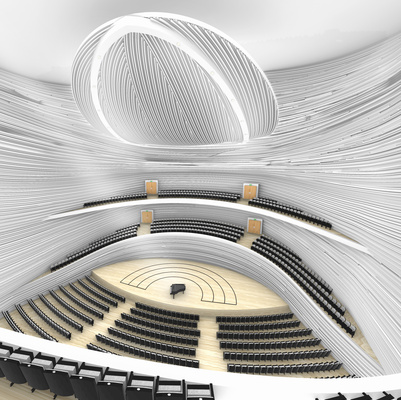
ARCHITECTURAL SCREEN
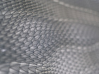
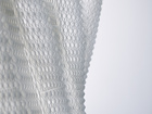
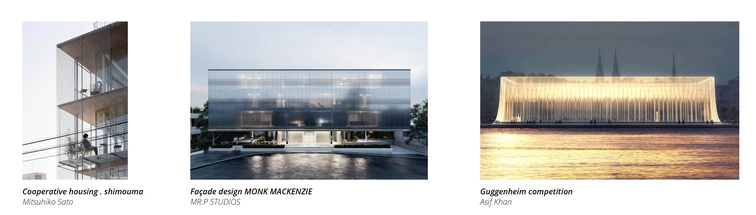
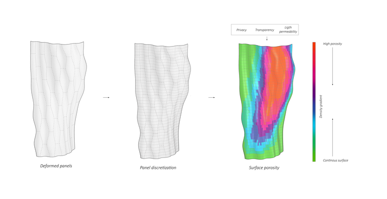
The architectural screen is an object that has a history of being quite exploratory with new techniques or materials or technologies. Screens that are used in architecture offer a very flexible division of spaces. They are smart because they allow an architecture that is efficient in terms of construction and quick to reconfigure. We saw the screen as an artifact that is within the scope of what we could be able to produce given our manufacturing constraints and the time-frame of the semester. It is an artefact that can be freestanding, has a certain kind of scale, while still being an important element of an architecture. The idea of graded surfaces enables a more sophisticated way to create relationships between the sides of the screen. Thin continuous surfaces function as a light diffuser and offers a higher degree of privacy while more porous areas of the screen have higher light permeability and create playful light and shadow effects. The design- and manufacturing methods allow dynamic transitions between contrasting conditions and complex doubly-curved shapes.
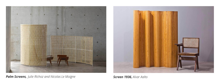
We see that in architecture there is more and more a move towards the idea of a soft screen as a way of creating a multi layered approach to the environmental enclosure. In the broader context of this project we see an immediate relevance for the methods developed, that in addition can bring in the idea of design orientated, multi criteria grading. AM technology does not require costly and labor-intensive measures such as formwork, nor the waste that is produced through various subtractive fabrication methods. Instead, complexity comes only at the cost of computation.
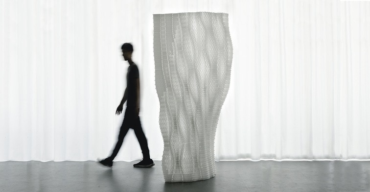
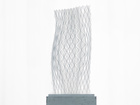
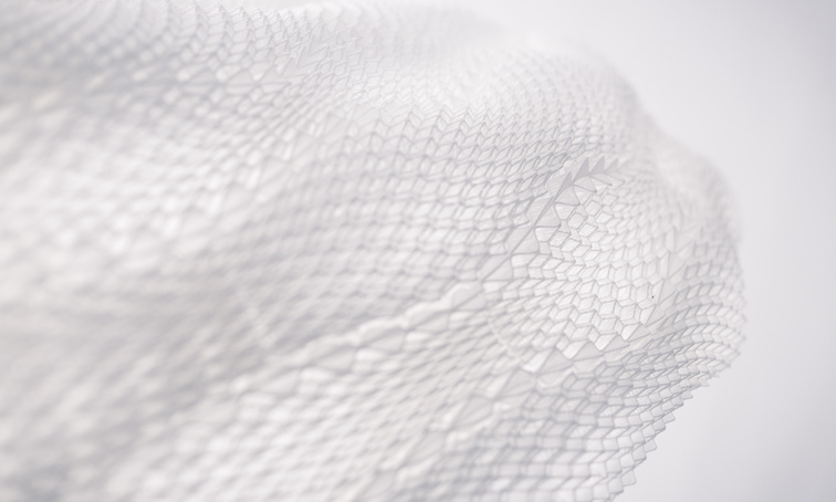
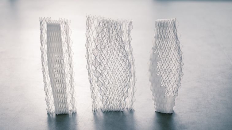
THE LIGHTSCAPE SCREEN
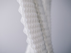
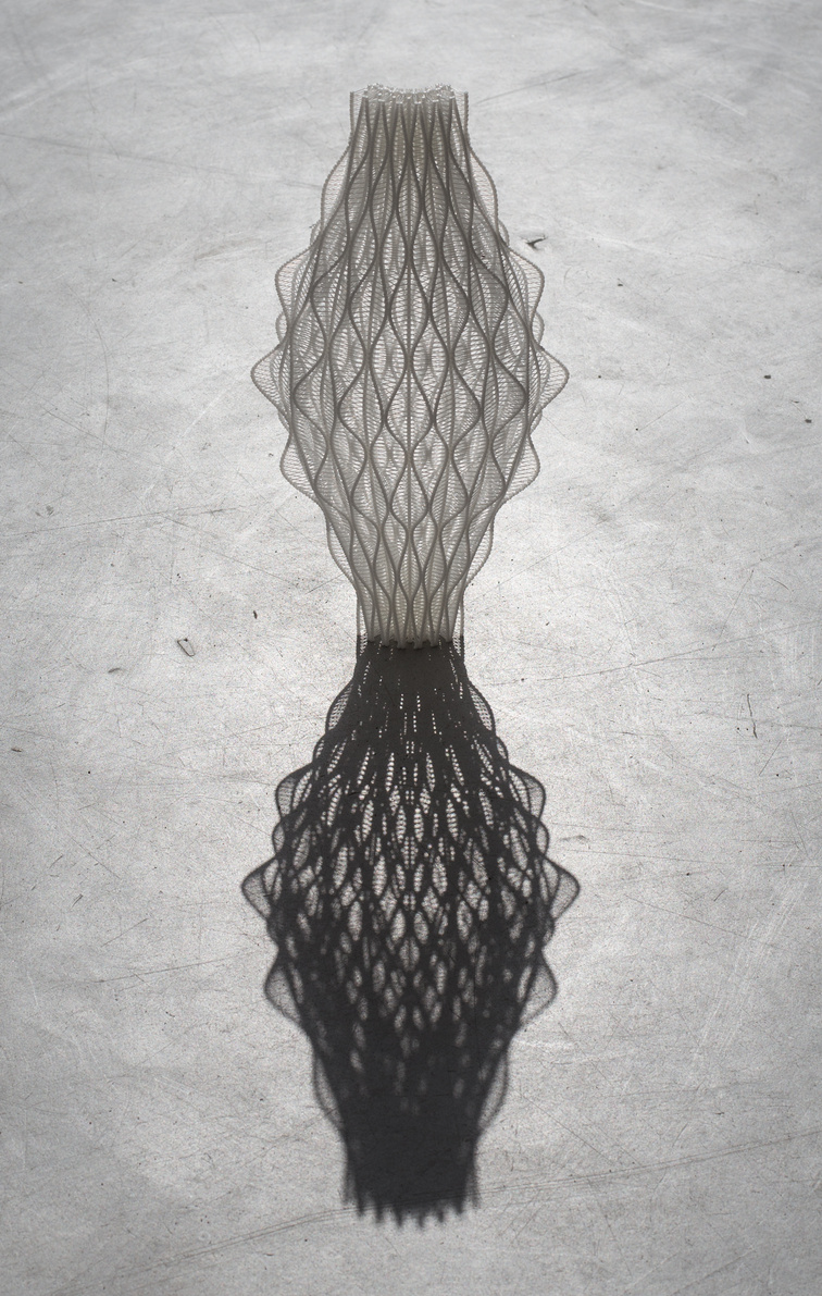
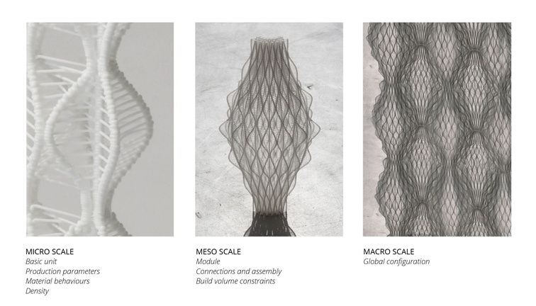
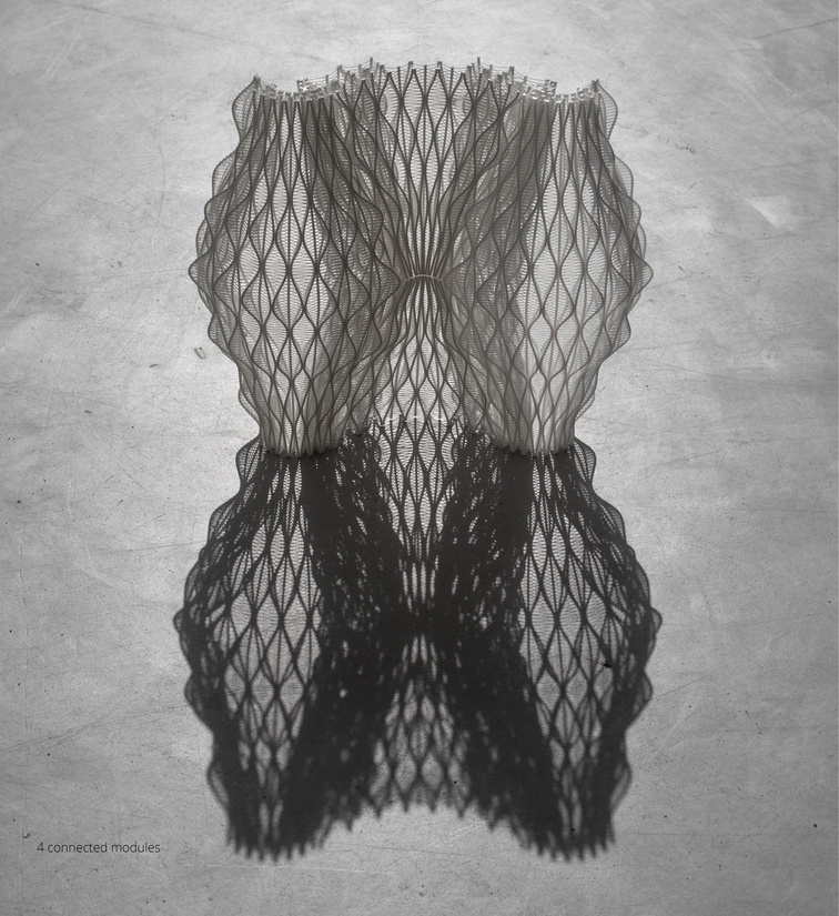
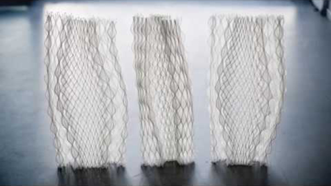
With the Lightscape Screen our goal was to create a one-to-one artefact that can be applied to divide spaces and at the same time function as a demonstrator of the methods developed in this project. The constrained build volume meant that the screen needed to be assembled by units no larger than what the 3D printer allowed. Sinusoidal shaped modules were chosen as they have a shape that was achievable within the constraints of our methods, they made a good base for connections, the shape accommodates variation in structural density, and the undulation gives a dynamic and seamless impression of the assembled surface. The production of the Lightscape Screen refers to three scales that each describe interdependent functionalities and considerations within the design system.
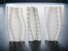
COMPRESSION TESTING
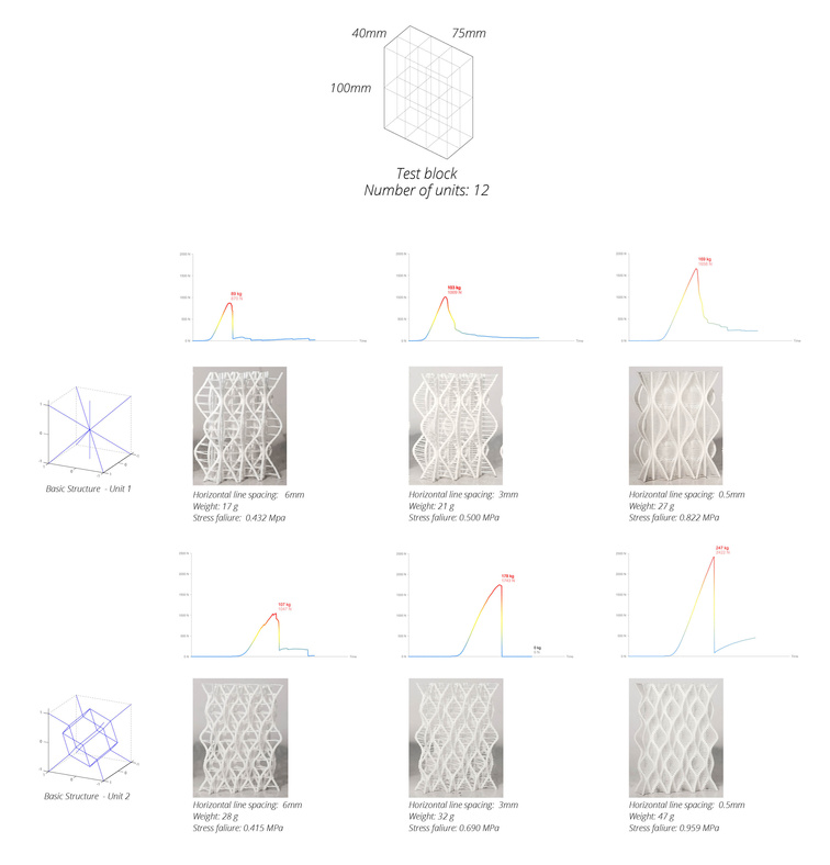
Compression testing was performed on equally sized blocks each containing 12 structural base units. Two units with different spatial configurations were used. Horizontal, single lines of filament were used as a secondary structural system to restrain the primary structure. For the compression testing, three different densities of restraining lines were tested for both base units. Generally, the second unit could take more compression and both units increased in strength when the density of horizontal lines increased. An interesting observation was that the change from ductile to brittle failure when this density increased.
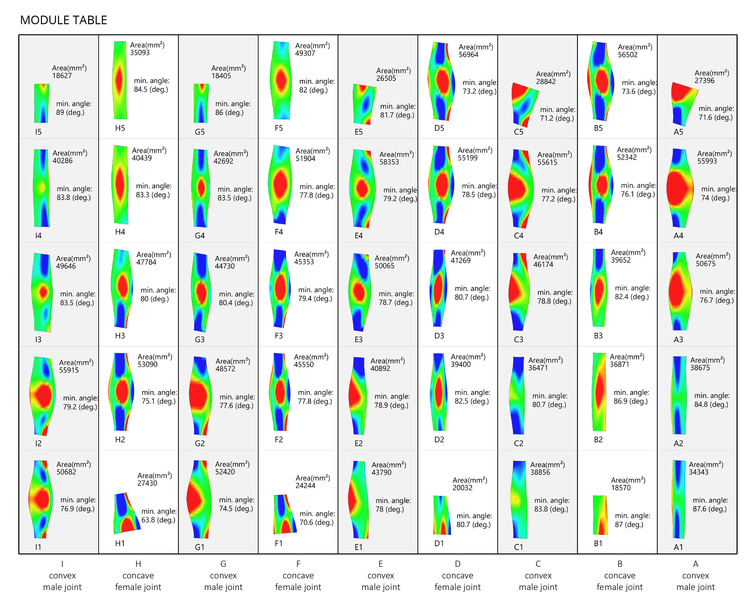
JOINING
The limited build volume made it necessary to figure out solutions for connecting modules. After having considered different joining principles, we found that the structures undulating nature provided a good base for interlocking. A system of interlocking male-female joints was developed that do not require the use of adhesives. The female joint was made moderately flexible to ease the assembly. In combination with the sinusoidally shaped modules this gives a dynamic and seamless impression. The complete screen consists of 45 unique modules. The computational workflow and the manufacturing methods allowed us to consider the connection details only once and replicate the solution, although the module changes its form in every instance. This enables the production of highly complex modular geometry that doesn’t incur increased production time or cost.
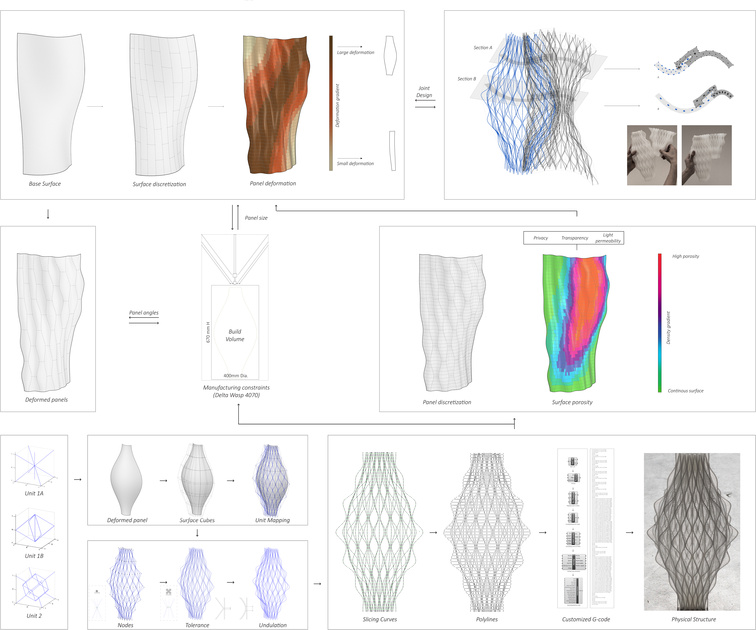
WORKFLOW
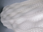
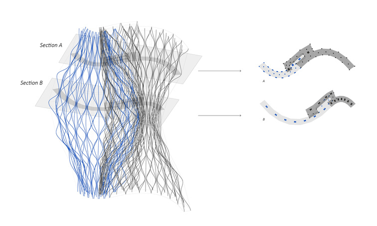
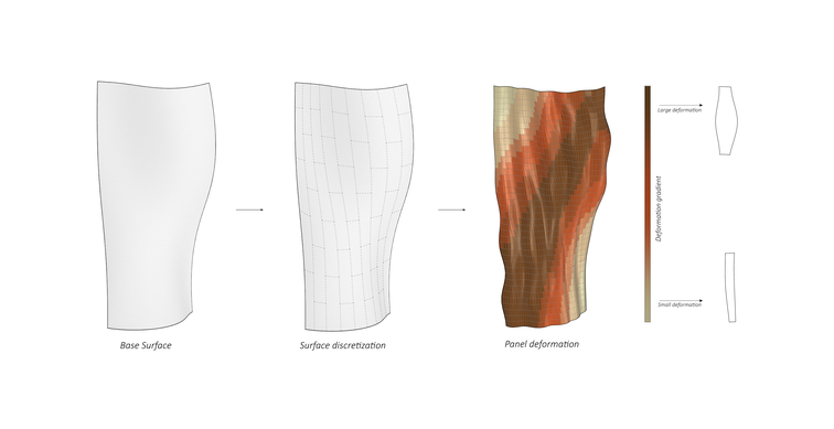
A doubly-curved surface was used as the target geometry of the screen. The size and angular optimization of the modules was aided by an evolutionary solver to make sure that modules would not exceed their respective manufacturing constraints. A gradient was applied to steer the level of deformation applied to each module. This resulted in in areas of higher and more homogenous structural density. Another gradient was applied to map the density of the restraining, horizontal lines, to each basic structural unit. The density varies from continuous surface to a 6mm spacing between lines. The two latter steps resulted gradual variations in the porosity of the surface.
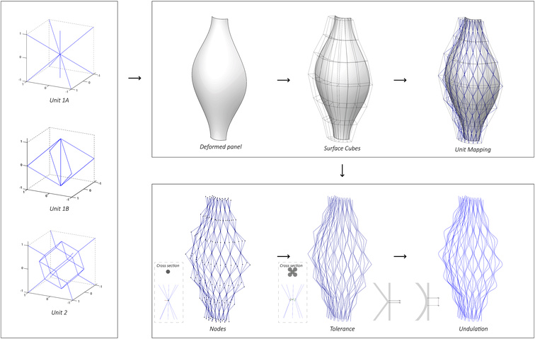
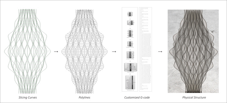
A method of unit mapping was used to apply structural units to each module. The basic structural units were defined within a unit cube with equal edges. These units consist of a series of linear members within the unit cube that meet at node points, like in a 3D space frame. The topology of a structural unit refers to the number of members and how they are connected, while its geometry refers to the locations and orientations of the node points in 3D space. The module surfaces were populated with boxes, and the structural unit was referenced into each one of the boxes. There is a lot of geometric variation in the surface cubes of one single module, due to the complexity of the target surface, that each differ from the unit cube. The method of unit mapping ensures that the units maintain a constant topology and so connects seamlessly to its neighbors despite geometric variation in each instance. This also ensures that neighboring modules can be produced as a seamless whole. Unit 1A and 1B was used for joints and secondary skin, while unit 2 was used for the primary skin. After the units were mapped to the surface, equal spacing was ensured between members in every node point due to tolerance. Linear members were replaced by undulating curves that meet in the same node points. This increases the connection area in which two members meet, and so ensures stronger connections. The resulting curves was then sliced into horizontal layers of points. According to the porosity gradient described above, a given interval of these layers are weaved into horizontal polylines. Next, the points and lines are sorted and translated into machine code. A series of grasshopper components was developed to ease the workflow and enable us to customize all production parameters and write customized G-code.
MOTIVATION FOR THE RECIPIENTS OF THE UN SUSTAINABILITY PRIZE
A principle impediment to exploiting the true creative potential of Additive Manufacturing remains the software for generating machine instruction. By developing a deep understanding of machine control parameters, and their influence on the mechanical properties of material, Stian Vestly Holte and Kit Wai Chan have been able to open radically novel creative opportunities in 3D printing for design and architectural contexts. Their thesis project – Design Through Process Control: a novel design methodology for additive manufacturing – is at once a systematic study, a exquisite aesthetic display contemporary making and a call-to-arms for understanding and taking full control of high-technology. The concerns of their project reflect those of UN Sustainbility Goal 9, which aims at building resilient infrastructure, promoting inclusive and sustainable industrialisation and fostering innovation. By providing tools for self-authorship of 3D printing toolpaths, working with material developed from corn starch and operating with the functional and mechanical grading of mono-material filament – this project offers tangible insights that address Goal 9’s concerns with inclusion, sustainable industrialisation and innovation.
Phil Ayres/CITAstudio: Computation in Architecture